The MAF (Mass Air Flow) sensor plays a critical role in engine performance by measuring the amount of air entering the intake system. Based on this data, the ECU calculates the correct air-fuel mixture. When this sensor becomes faulty, it can lead to poor fuel economy, rough idle, hesitation during acceleration, and even engine stalling.
Learning how to test a MAF sensor with a multimeter helps you confirm whether the issue is electrical or related to contamination or airflow problems. This is one of the most practical diagnostic methods used in both home garages and professional workshops because it provides direct insight into the sensor’s electrical behavior.
However, before testing, it is important to understand that not all MAF sensors work the same way. Some produce a variable voltage signal, while others generate a frequency-based signal. This difference affects how readings are interpreted during diagnosis.
Lear More: How to Test a MAF Sensor Without a Multimeter
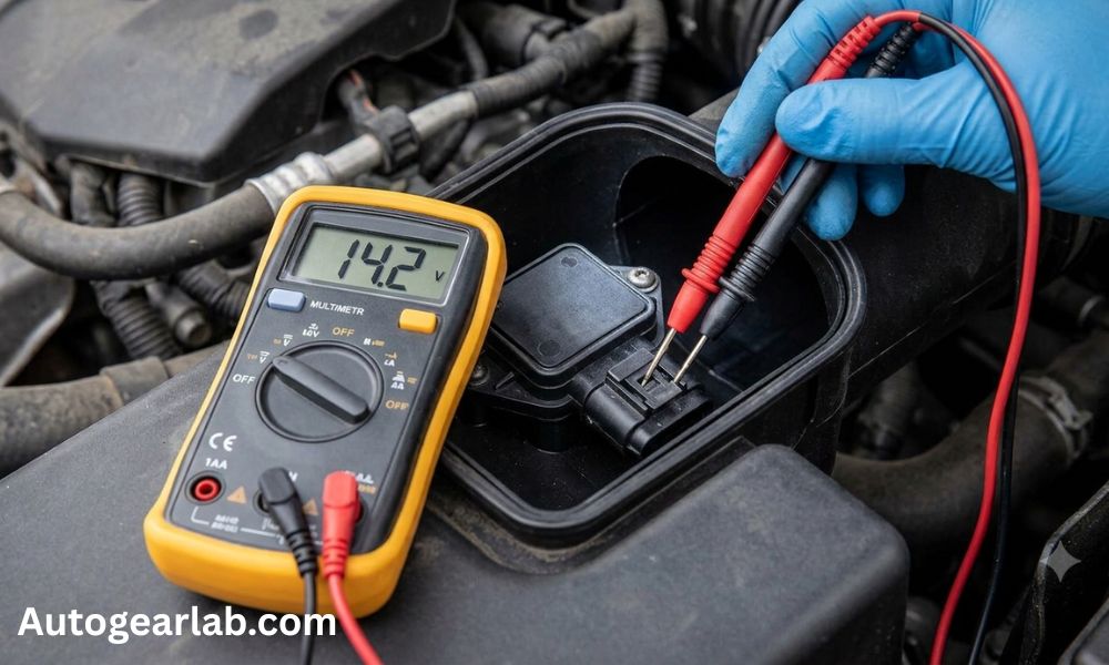
Tools Needed for MAF Sensor Testing
Before starting the test, make sure you have the following tools ready:
- Digital multimeter (auto-ranging preferred)
- Vehicle-specific wiring diagram
- Basic hand tools (for accessing the sensor)
- Safety gloves (optional but recommended)
A wiring diagram is especially important because MAF sensor pin layouts differ across manufacturers. Without correct pin identification, testing results may be misleading or incorrect.
Common Symptoms of a Faulty MAF Sensor
Before using a multimeter, it’s helpful to recognize symptoms that suggest a possible MAF issue:
- Rough or unstable idle
- Poor acceleration response
- Increased fuel consumption
- Engine hesitation or stalling
- Check Engine Light (often with codes like P0100–P0104)
These symptoms alone do not confirm failure, but they indicate that further testing is necessary.
Understanding MAF Sensor Wiring
To properly test a MAF sensor, you must first understand its basic wiring structure. Most MAF sensors have three to five wires depending on the design.
1. Power Wire
This wire supplies voltage to the sensor, typically 12V or 5V depending on the system.
2. Ground Wire
Provides a return path for electrical current. A weak ground can cause inaccurate readings or sensor malfunction.
3. Signal Wire
This is the most important wire during testing. It sends airflow data to the ECU in the form of voltage or frequency.
4. Additional Wires (if present)
Some MAF sensors include intake air temperature (IAT) sensors or reference circuits.
Understanding these wires is essential before moving to electrical testing because incorrect probing can damage the sensor or produce false readings.
How MAF Sensors Communicate with the ECU
MAF sensors do not simply turn on or off—they continuously measure airflow and send real-time data to the ECU. Based on engine load, the signal changes dynamically.
At idle, airflow is low, so the signal output is also low. When the engine accelerates, airflow increases, and the sensor adjusts its output accordingly.
This behavior is what we evaluate using a multimeter in the next steps of the diagnostic process.
Safety and Preparation Tips Before Testing
Before you begin any electrical testing:
- Ensure the engine is off when checking wiring continuity
- Avoid damaging insulation when back-probing wires
- Do not force multimeter probes into connectors
- Keep hands and tools away from moving engine parts during running tests
- Always verify correct wire identification using a diagram
Proper preparation ensures accurate results and prevents accidental damage to the sensor or ECU.
What You Will Learn in the Next Part
In Part 2, we will go step-by-step into the actual multimeter testing process, including:
- Checking MAF sensor power supply
- Testing ground connection
- Measuring signal output
- Performing a snap throttle response test
- Interpreting real diagnostic readings
This is where you will learn how to practically confirm whether your MAF sensor is working correctly or failing electrically.
Multimeter Testing Procedures (Power, Ground, and Signal Tests)
In this section, we move from theory to practical diagnosis. Now that you understand the wiring and behavior of a MAF sensor, the next step is to test its electrical health using a digital multimeter. These tests will help you confirm whether the sensor is receiving proper power, has a good ground, and is producing an accurate signal.
Step 1: How to Check MAF Sensor Power Supply
The first and most basic test is verifying that the sensor is receiving electrical power.
Procedure:
- Turn the ignition key to the ON position (engine off).
- Set your multimeter to DC voltage mode.
- Locate the power wire using the wiring diagram.
- Back-probe the connector carefully without damaging insulation.
- Place the black probe on a good ground point and the red probe on the power wire.
Expected Result:
- Most vehicles will show around 12 volts (battery voltage)
- Some sensors may operate on a regulated 5 volts reference
Interpretation:
- Correct voltage present: Power supply is OK
- No voltage: Possible blown fuse, wiring issue, or ECU power failure
- Low/unstable voltage: Weak connection or corrosion in the circuit
Step 2: How to Test MAF Sensor Ground Connection
A weak or broken ground is one of the most common causes of incorrect MAF readings.
Procedure:
- Switch multimeter to continuity or resistance mode.
- Turn ignition OFF.
- Connect one probe to the ground wire pin.
- Connect the other probe to the battery negative terminal.
Expected Result:
- Continuity beep OR very low resistance (close to 0 ohms)
Interpretation:
- Good continuity: Ground is healthy
- High resistance or no continuity: Bad ground connection or damaged wiring
- Intermittent reading: Loose connector or corrosion in ground circuit
Step 3: How to Test MAF Sensor Signal Output
This is the most important test in the multimeter method because it shows how the sensor reacts to airflow.
Procedure:
- Start the engine and let it reach normal operating temperature.
- Set multimeter to DC voltage mode.
- Back-probe the signal wire while keeping the connector plugged in.
- Observe readings at idle.
- Slowly increase engine RPM and monitor changes.
Expected Behavior:
- At idle: low and stable voltage
- As RPM increases: voltage should rise smoothly
- During deceleration: voltage should drop gradually
Interpretation:
- Smooth increasing signal: Sensor is working properly
- Flat or no change: Faulty MAF sensor or wiring issue
- Erratic jumps or drops: Contaminated or failing sensor
- Delayed response: Weak or aging sensor element
Step 4: Snap Throttle Response Test
This test checks how quickly the MAF sensor reacts to sudden airflow changes.
Procedure:
- Keep multimeter connected to signal wire.
- Quickly press the accelerator pedal (brief throttle snap).
- Observe how fast the reading changes.
Expected Result:
- Immediate rise in voltage when throttle is pressed
- Quick return to baseline when released
Interpretation:
- Fast response: Sensor is healthy
- Slow response: Dirty or aging sensor
- No response: Electrical failure or dead sensor
Step 5: Cross-Check with Real Conditions
Even if multimeter readings look normal, real-world behavior matters.
Watch for:
- Engine hesitation during acceleration
- Rough idle despite normal voltage
- Poor fuel economy
- Check engine light codes (P0100–P0104 range)
If symptoms exist but multimeter readings are normal, the issue may be related to:
- Intake air leaks
- Dirty throttle body
- Fuel system imbalance
What You Will Learn in Part 3
In the final section, we will focus on:
- How to interpret all test results together
- Common mistakes during MAF diagnosis
- When to clean vs replace the sensor
- Final troubleshooting decision flow
This will help you confidently determine whether the MAF sensor is truly faulty or if another system is causing the issue.
Result Interpretation, Mistakes, FAQs, and Final Diagnosis
In this final section, we combine all test results and turn them into a clear diagnosis. A multimeter alone does not “confirm” a bad MAF sensor—you must interpret power, ground, and signal behavior together to reach the correct conclusion.
How to Interpret the Results
After completing all multimeter tests, your readings will generally fall into one of these categories:
1. Sensor OK
If power supply is correct, ground is stable, and signal voltage responds smoothly to RPM changes, the MAF sensor is likely functioning properly.
Key signs:
- Stable idle reading
- Smooth voltage increase with RPM
- No erratic fluctuations
- Normal engine behavior during throttle response
👉 In this case, the issue is likely elsewhere (vacuum leak, fuel system, ignition system, or throttle body).
2. Dirty Sensor
If readings are inconsistent but not completely failed, contamination may be affecting accuracy.
Key signs:
- Slightly delayed signal response
- Small fluctuations in voltage
- Engine hesitation under load
- Improvement after cleaning
👉 Cleaning with proper MAF cleaner may restore normal operation.
3. Wiring Issue
If power, ground, or signal is missing or unstable, the problem is likely electrical rather than the sensor itself.
Key signs:
- No voltage at power wire
- Poor or no continuity in ground
- Intermittent signal loss
- Random voltage drops
👉 Inspect connectors, wiring harness, fuses, and ECU connections.
4. Replace Sensor
If all wiring checks are correct but signal output is still incorrect or unresponsive, the sensor is likely internally damaged.
Key signs:
- No change in signal during RPM increase
- Erratic or frozen readings
- No improvement after cleaning
- Symptoms confirmed across multiple tests
👉 Replacement is the final step after confirming all other systems are healthy.
Common Mistakes When Testing a MAF Sensor
Many incorrect diagnoses happen due to simple testing errors. Avoid the following:
Wrong Cleaner Usage
Using carb cleaner, brake cleaner, or harsh chemicals can permanently damage the sensing element.
Touching the Sensing Wire
Even light contact can break or miscalibrate the delicate sensor wire.
Skipping Live Data
Multimeter readings alone do not show real driving conditions. Ignoring OBD2 data leads to incomplete diagnosis.
Ignoring Intake Leaks
Unmetered air entering the system can mimic a bad MAF sensor even when the sensor is healthy.
Frequently Asked Questions
Can a multimeter fully test a MAF sensor?
No. It can verify electrical signals, but not full airflow accuracy under all driving conditions.
What is the normal voltage for a MAF sensor?
It varies by vehicle, but typically:
- Idle: low voltage (around 0.5V–1.5V in many systems)
- Higher RPM: increasing voltage
Can a bad MAF still show normal voltage?
Yes. A sensor can pass basic voltage checks but still provide incorrect airflow readings.
Should you clean or replace first?
Cleaning is always the first step unless there is clear electrical failure or physical damage.
How long does testing take?
Basic multimeter testing usually takes 20–40 minutes depending on access and experience.
Conclusion
Testing a MAF sensor with a multimeter is a reliable way to identify electrical faults, but it should always be part of a complete diagnostic process. The best approach combines:
- Multimeter testing (power, ground, signal)
- OBD2 live data analysis
- Physical inspection and cleaning
A proper step-by-step diagnosis helps avoid unnecessary part replacement and ensures the real issue is fixed correctly the first time.